 FR
FR


How to restore a non-booting iPad: replacing PMIC in simple steps
07-11-2024 • Temps de lecture: 4 min
As a repair store, when you receive an iPad that won't boot up due to a faulty power management IC (PMIC), determining the right approach can be quite challenging. The intricacies of modern tablets and sensitive electronics require careful inspection and precise execution of the repair. Find out in this blog how to replace the PMIC step by step, carefully remove the motherboard without damaging other components, and apply the necessary soldering techniques to restore the iPad to optimal operation.
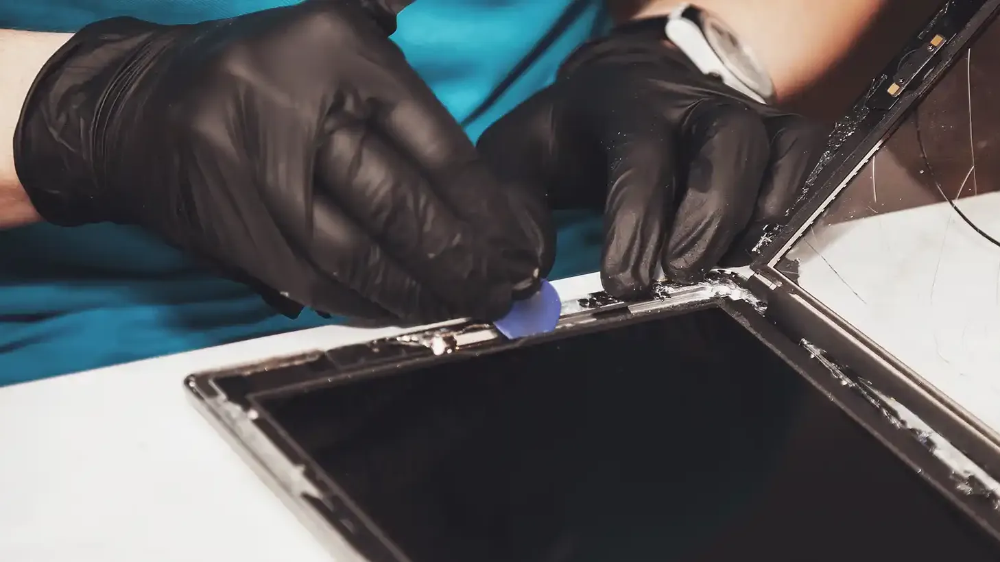
Step 1: Preparation of the motherboard
Before starting the repair, it is advisable to work on an antistatic surface. This will prevent damage to the electronic components. Once you have prepared this mat, you can start removing the motherboard from the iPad. This requires disconnecting various components and cables:
Remove screws: Start by removing the screws at the charging port, battery and brackets at the top.
Disconnecting cables: Disconnect all coax cables and flexka cables from the board. Use a little isopropyl alcohol to loosen the glue along the edges, this is a handy tool you can use to apply the alcohol. Do this carefully, it is important to be careful with the flex cables and components on the board as you lift them.
Step 2: Removing the Faulty PMIC
A PMIC sits close to other small parts, making its removal more difficult. Here are a few tips to safely remove the IC without damaging other parts:
Apply heat protection: Place heat shielding around surrounding components, especially around the CPU, to prevent overheating.
Using hot air: Add some flux to the PMIC and use a hot air station to heat the PMIC to the point where you can carefully remove the IC.
If small components shift during heating, they can be put back in place with tweezers and some extra solder.
Step 3: Preparing the Location for the New PMIC
After the defective PMIC is removed, the location on the motherboard must be properly prepared for the installation of the new PMIC.
Cleaning and preparation: Apply a layer of solder paste 138°C and use a soldering iron to carefully mix the existing solder residue.
Solder removal: Use a solder wick to remove excess solder and make sure the pads are clean and ready for the new PMIC.
If necessary, turn the board in different directions for a comfortable working position and to properly control the soldering processes.
Step 4: Installing the New PMIC
This is an important step in the repair process and requires accuracy and attention.
Positioning the PMIC: Align the new PMIC in the correct location. Look at the markings or pads on the motherboard that indicate where to place the PMIC. Often there are small dots or lines that help with alignment.
Apply heat: Gently heat the PMIC so that the solder balls adhere well to the pads. Pay close attention that the IC stays in place without shifting.
If small components such as capacitors have shifted, reheat them to get them back in place.

Step 5: Replace and Test the iPad Motherboard
With the new PMIC installed, it's time to put the board back in the iPad enclosure and test the iPad.
Reconnect: Place the motherboard back in the frame, align the battery and charging port, and attach the screws.
First test: Connect the display and digital connectors and remove the battery protection. When you connect the iPad, you should now see a charging icon appear.
Testing for battery percentage: Let the iPad charge for a few minutes. Make sure the battery percentage increases, confirming that the device is charging properly.
Conclusion
Replacing a broken power management IC (PMIC) in an iPad is a difficult but important job for repair stores. Important steps include using the right tools, such as a hot air station and solder paste, and making sure everything is aligned and soldered properly. After installation, it is important to test the iPad to make sure it is working and charging properly again. With these instructions, you as a repairman can get the iPad working again and increase customer satisfaction.
Keep up with the latest developments and updates by following our blogs and following us at LinkedIn.